Now that you have an
understanding of basic gates it is
time to combine them into more complex devices. Gates can have more
than
two inputs, and gates can be combined to create more powerful modules.
The following examples will familiarize you with just a few of the many
possible combinations that can be built by combining simple gates into
useful devices.

 |
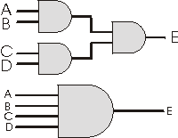
Both of these figures show the same device:
4 INPUT AND
GATE
All 4 inputs
must be logic 1 for the output to
be a logic 1. Any other combination will output a logic 0, or OFF state.
|
 |
This would be a: 4
INPUT NAND GATE
All four
inputs would have to have a logic 1 state
for the device to output a logic 0 state. Any other combination will
produce
a logic 1 or ON condition.
|

Up to this point a gate would change it's output depending on the state
of it's inputs. Gates can also be built that require data to be clocked
in, or they can have a control line to deselect them from a circuit.
(To
turn them off.) The control line can force the device to go into a HIGH-Z
state. HIGH-Z
is when the
output of the gate goes into a very high resistance condition that will
effectively remove the gate from the circuit. The output of the gate is
so high that it becomes isolated and ignored by the other components
attached
to it.


|
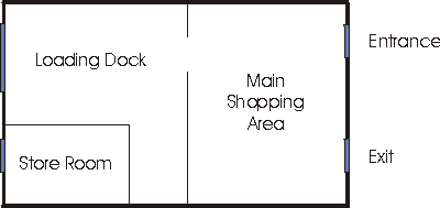
| Figure 1: The Downtown General Store |

In figure #1 above, we have a new customer. They have requested that
we build an alarm system for them to prevent burglars from steeling
their
merchandise. At night the alarm system will monitor all four doors, two
in the front of the store, and two at the rear of the store. If any
single
door is opened, the system should sound an alarm and summon the police.
During the day we have a different situation
however... we don't want
to summon the police every time a customer enters or leaves the
building
through the front entrance or the front exit. We could simply switch
the
alarm system off, but this would leave the store room and the loading
dock
unprotected. What we need is an alarm that is intelligent enough to
monitor
the back doors, but also ignore the front doors during the day when the
store is open.


|
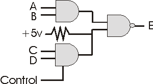
| Figure 2 : Our Custom Burglar Alarm |

Figure #2 shows the system we designed. The alarm has four
inputs
labeled A, B, C,
and D as well as one
output labeled E.
We will use switches on the doors to send a signal to our device. 5
volts
will represent a logic-1 state, and 0 volts will represent a logic-0
condition.
The table below will show you the connections and the expected
signals.

| Downtown
General Alarm Connections |
| A |
Loading Dock Door Switch |
Open = 0v, Closed = 5v |
| B |
Storage Room Door Switch |
Open = 0v, Closed = 5v |
| C |
Front Entrance Door Switch |
Open = 0v, Closed = 5v |
| D |
Front Exit Door Switch |
Open = 0v, Closed = 5v |
|
Control
|
Connected to a key switch marked
"DAY" and "NIGHT"
|
DAY = 5v, NIGHT = 0v
|
| E |
Output to warning lights and police |
OKAY = 0v, ALARM = 5v |

Now let's go see how the alarm
works. The next page contains
a JavaScript model of our alarm system. You can click on the doors to
open
and close them, and you can set the alarm to DAY or NIGHT mode to see
what
happens. This should help you to better understand how the gates
function,
and how the high-z control line works.
|