PUMA Robot - DXF to Movement Experiments
Using Visual BASIC 6 to convert
data into drawing commands for the PUMA robot arm
I created a DXF file that goes from ( 000,000 ) to ( 200,200 ) in other words, is 200mm in size. DXF Files are a standard drawing file for many CAD programs including AutoCAD.
We should be able to position the arm somewhere which will allow at least 200mm x 200mm of movement, or just under 8 inches. The next step was to run the DXF2XYZ.EXE program on the file to convert it to a series of XYZ coordinates... in this case the program was told to ignore the Z axis and just produce an X/Y file for simplicity. The output includes a 0 or 1 at the start to show if the PEN should be up (0) or down (1). A sample of the file looks like this:
0,0.000000,0.000000
1,200.000000,0.000000
1,200.000000,200.000000
1,0.000000,200.000000
1,0.000000,0.000000
0,49.214731,174.987664
...
...
1,200.000000,0.000000
1,200.000000,200.000000
1,0.000000,200.000000
1,0.000000,0.000000
0,49.214731,174.987664
...
...
This is useful... not not something that we can directly control the PUMA with... so I wrote a VB6 program to convert it to PUMA CODE... (VAL Programming Language) movements like this...
APPRO
ORIGIN, 50
MOVE ORIGIN
TYPE CONVERTED DATA STARTS HERE
TYPE -------------------------------
TYPE PEN UP
DRAW 000.000000, 000.000000, 020.000000
DRAW 000.000000,000.000000,000.000000
TYPE PEN DOWN
DRAW 000.000000, 000.000000,-020.000000
DRAW 200.000000,000.000000,000.000000
DRAW 000.000000,200.000000,000.000000
DRAW -200.000000,000.000000,000.000000
DRAW 000.000000,-200.000000,000.000000
TYPE PEN UP
...
...
In theory we should be able to define a point called ORIGIN and the robot should move to the proper coordinates to draw the image as it exists on the DXF file. I actually expect it to be upside-down... and if it is, we will put a correction into the VB6 file to reverse the Y-Axis coordinates. (Make them negative if positive, etc.) Then we relocate the ORIGIN and try again.
To see if the file is parsing okay, I also spit out a LOG file which is more human readable... just something that I could compare against the original XYZ file.
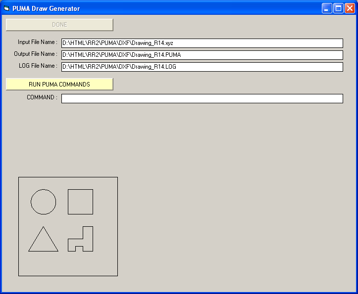
Screen
Shot of the Version 1 program after an XYZ conversion.
As you can see, the DXF was reproduced on the screen above. This means the data was sucessfully recovered, the PEN up/down action should be correct, and in theory it should make a good set of PUMA control codes. When we tested the file, it worked very well the first time. There was a minor issue with the PEN up/down position... an extra line of code that I had to remove... but otherwise we were very pleased with the output.
If you want to play with this code, I have it all bundled here...
http://rutherford-robotics.com/PUMA/DXF/
You can download the XYZ file and parse it yourself to create the PUMA file and the LOG file. You should be able to create your own DXF and run the DXF2XYZ.EXE program on it as well. Ise a mm scale as that's what the PUMA uses... and I would say to limit the drawing area to not more than 200mm to start. (Possibly less if you have a PUMA 260 series machine.)
The VB6 code as I currently have it is here: http://rutherford-robotics.com/PUMA/DXF/VB6_XYZ_2_PUMA_V1.zip
The XYZ program is not properly parsing circles... so I had to cheat and draw a 100 sided polygon to get something that looked like a circle. Once we find that we can properly control the arm, the next step is to process G-Code to do the same thing... at least with the G-Code we can get G02 and G03 commands for the circles and arcs. When we have that knocked out... in theory we should be able to unbolt the gripper and install a Dremel tool then cut loose on some foam.
For the moment, we did some very successful tests as this video clearly shows. This file was really testing the limits of the original 1980's controller... the text file was 57K in size... but it all fit in there. The next step is to have the PC feed the robot one line at a time... this way there will be no size limit and we can create some very complex designs.
I'll keep you posted!
Jerry